A cryogenic permanent magnet oscillator (CPMU) with magnetic period λu=20 mm and total length L=1.5 m is selected as the beam line source for BL02U2 to meet the demand of high energy range. The brightness profile is calculated using XOP simulation software with high brightness and good continuity. The spectral flux into the 80 μrad × 40 μrad center cone is about 3.8×10¹⁴ phs/s/0.1%BW at K=1.37 (corresponding toE=10 keV). The source size is about 380×23 μm2, and the divergence of the source is about 60×16 μrad2 at 10 keV.
The beamline optics consist of the following main components: horizontal deflector mirror, double crystal monochromator (DCM), vertical focusing mirror and horizontal focusing mirror. During design, the beamline layout utilizes a minimum number of optical elements with good beam stability. A white beam slit located at 19.3 m from the light source limits the acceptance angle of the beamline to 0.08 mrad × 0.04 mrad. Behind the white light slit, a double-crystal monochromator (DCM) was used 20.86 m downstream of the source, and a double-crystal Si (111) monochromator was used, taking into account the energy resolution and energy range requirements. The total power on the first crystal is about 160 W, with a maximum power density of about 33 W/mm2, cryogenically cooled using liquid nitrogen. In the beamline, a monochromatic X-ray beam is focused on the sample spot through horizontal and vertical focusing mirrors. The vertical focusing mirrors are cylindrical mirrors with meridian bends, placed horizontally; the horizontal focusing mirrors, also with meridian bends, are placed laterally, with focus points at 46 and 51 meters, respectively. The two focusing mirrors also serve to suppress high harmonics. The focusing mirrors are made of silicon with heavy elemental coatings (Pt and Rh). For energies between 4.8 and 10 keV, the uncoated portion of the focusing mirror can be used, while for energies between 10 and 20 keV, the Rh coating is more suitable. The Pt coating is used for energies between 20 and 28 keV.
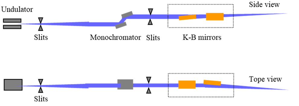
Optical design schematic and layout of surface diffraction beamline
According to the simulation of the SHADOW tracing program, the focused beam size of the beamline at 10 keV is about 140×72 m2, the photon flux at the sample position is about 1.45×10⁻⁴, the photon flux at the sample position is about 8.8×10¹² phs/s (10 keV/300 mA), and the beam divergence at the focal point is about 156×58 μrad2。
附件下载: